Engineering Project / 03
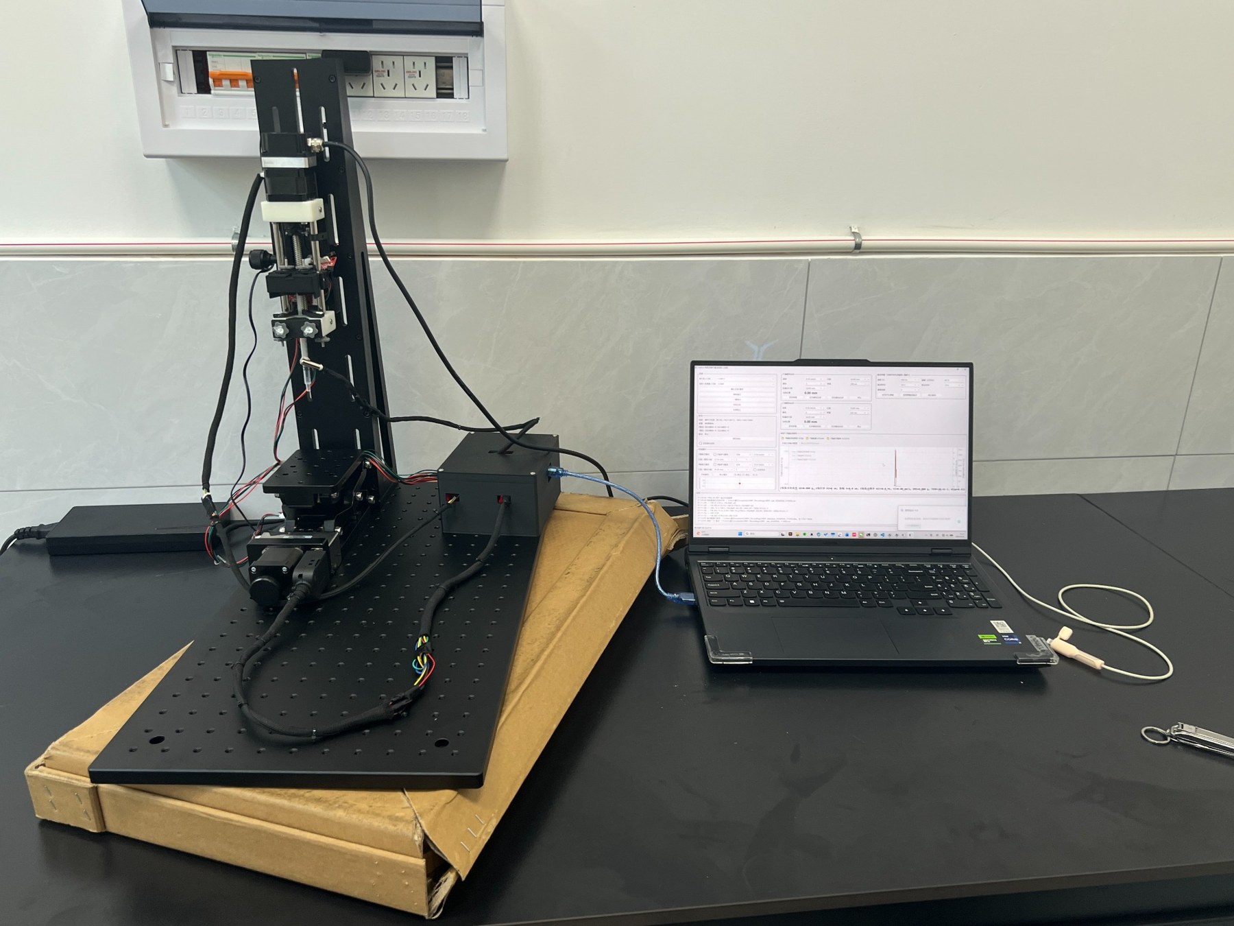
ElectromechanicalExperimentalPlatform.
A Python–MCU-based experimental system combining programmable X/Z motion, vibration excitation, sensor monitoring, and experimental data acquisition.
Designed as a hands-on platform for linking mechanical hardware, control logic, and a practical desktop interface.
Motion
X / Z Linear Axes
Controller
Python + MCU
Measurement
Vibration Sensing
Output
Data & Excel Export
01 / System Design
Connecting controlled motion with experimental observation.
The mechanical platform provides programmable positioning; the Python interface coordinates commands and captures vibration-related measurements. The principle schematic illustrates the intended capillary and bubble–particle experiment supported by this setup.
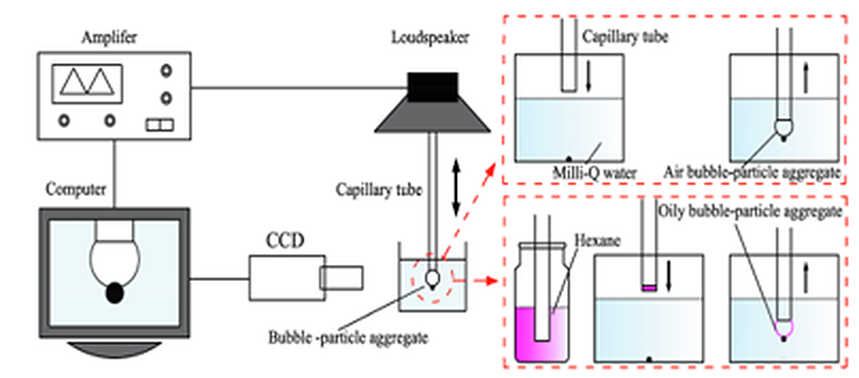
Experimental principle and target effect — capillary positioning, acoustic excitation, and optical observation. Schematic shows intended research operations, not measured experimental results.
Target Experimental Workflow
Capillary positioning
Use mechanical motion to place or reciprocate the working capillary with configurable travel and timing.
Vibration excitation
Configure excitation parameters to investigate the effect of mechanical or acoustic disturbance on the sample system.
Bubble–particle behavior
The schematic illustrates target aggregate formation and manipulation in an aqueous environment, including a hexane-assisted case.
Observation & recording
Visual/CCD observation is shown in the experimental concept; the developed software interface provides vibration monitoring and logs.
Control & data architecture
Control instructions and measurements are represented as two separate paths. Monitoring does not imply closed-loop actuation.
A — Motion command path
Python GUI
Parameters & commands
Serial / MCU
Command processing
Motor drivers
X / Z stage motion
B — Measurement & recording path
Vibration sensor
Measured signals
Serial acquisition
Data transfer
Python GUI
Plots, logs & export
02 / Hardware & Motion
A real mechanism behind every software command.
Stepper-driven linear motion, mechanical fixtures, and microcontroller communication were integrated into a working experimental arrangement. Motion settings in the GUI translate into configured travel, timing, and repeated sequences.
01
Mechanical & Actuation
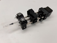
Two motor-driven motion axes, linear transmission elements, fixture integration, motion limits, and recurring experimental sequences.
X / Z MOTION · STEPPER MOTORS · MECHANICAL ASSEMBLY
02
Embedded Communication
An MCU-side motion-control interface coordinated with a Python supervisory application through serial commands and device-state information.
MCU · SERIAL COMMUNICATION · LIMIT MANAGEMENT
03
Coordinated Motion
Configurable travel, speed, dwell time, X/Z interpolation-related motion, and repeated sequences for experimental operation.
TRAJECTORY LOGIC · INTERPOLATION · CYCLIC MOTION
03 / Python Software
One interface for motion, vibration, and measurement.
I developed a Python desktop interface to centralize motor commands, experimental parameters, connection status, vibration monitoring, visualizations, and data export.
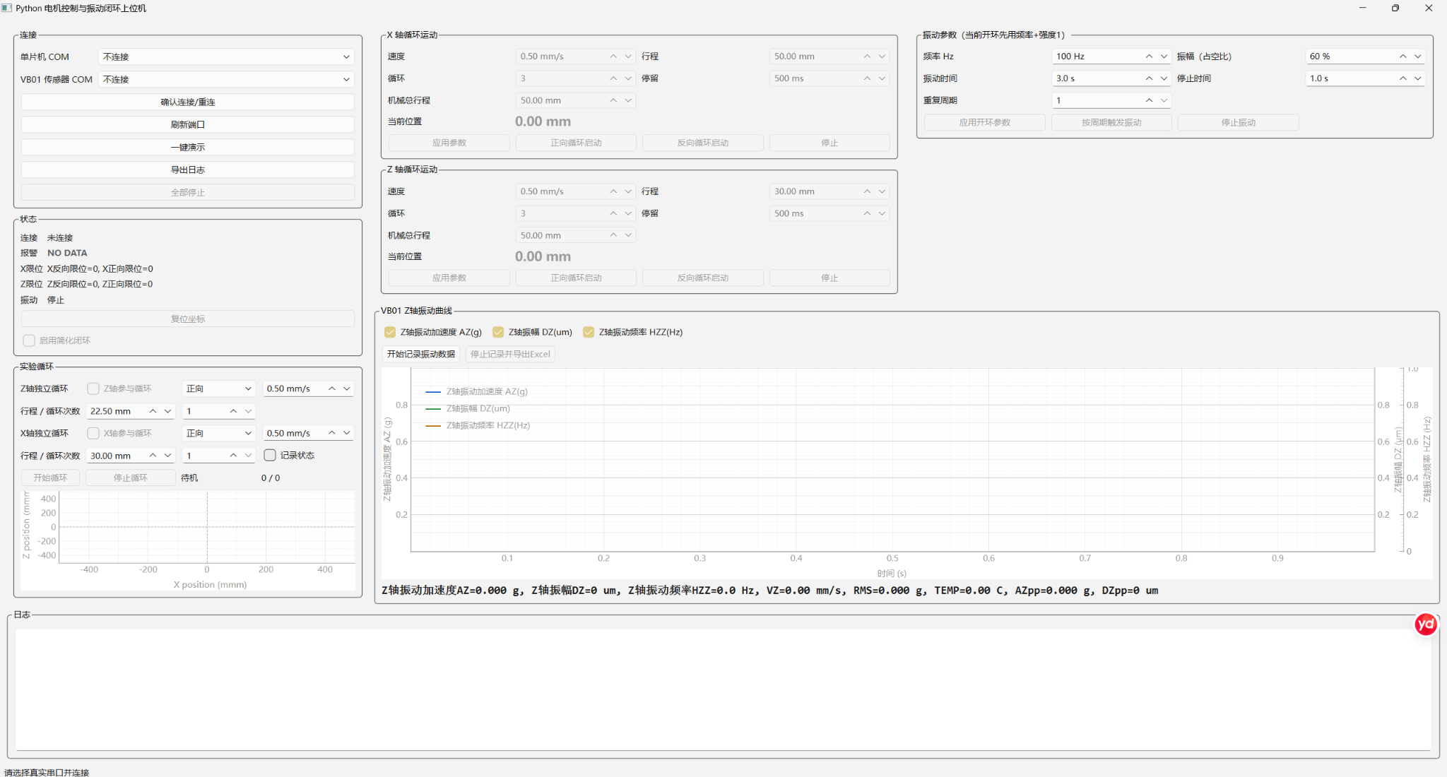
Actual application interface shown in a disconnected / idle state; the empty plots are interface placeholders, not experimental results.
Connection & State
Motor and vibration-sensor serial ports, device connection, alarms, and limits.
X/Z Motion
Travel distance, speed, dwell time, repeated cycles, and axis position displays.
Vibration Settings
Excitation frequency, duty cycle, run/stop duration, and cycle configuration.
Monitoring & Export
Vibration-related plots, system logs, and experimental record export to Excel.
04 / My Contribution
From assembled hardware to a usable experimental system.
This project brought together mechanical integration, Python development, MCU communication, motion sequencing, sensing, and experiment-oriented data handling.
Mechanical Integration
Built and assembled the experimental stage around X/Z motion, the working fixture, and vibration-related components.
Python GUI Development
Developed a desktop workspace for connection management, experiment parameters, motion controls, monitoring, and logs.
MCU Communication
Integrated serial commands and controller communication into the software–hardware operating workflow.
Motion Logic
Implemented configurable motion, X/Z interpolation-related functions, cyclic movement, and travel-limit management.
Vibration & Sensing
Integrated vibration configuration and sensor readings into a common monitoring and visualization interface.
Experimental Data
Organized live plots, operation logs, status information, and Excel-compatible data export for subsequent analysis.
What I Learned
Building an experiment also means designing the system that makes it controllable, observable, and repeatable.
The experience strengthened my interest in robotic mechanisms, embedded systems, instrumentation, and hardware–software co-design — a foundation I hope to build on in future research on digitally fabricated adaptive devices, functional materials, and intelligent mechanical systems.